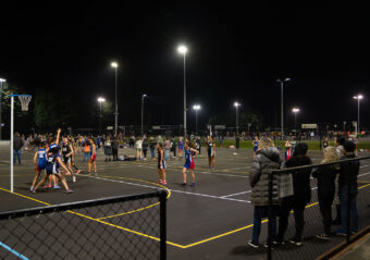
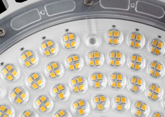
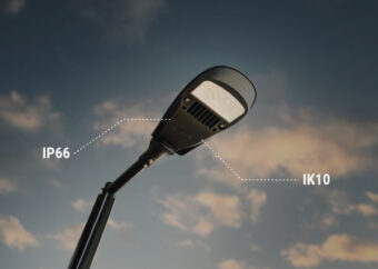
A Light Emitting Diode (LED), also referred to as SSL (Solid State Lighting), is an electronic device (chip) that produces light when an electrical current is passed through it.
LED chips are inherently low-voltage devices that need additional electronic components to convert the line-voltage 240V AC to the low DC voltage needed for the LEDs. These electronics units also interpret control signals and dim the LEDs accordingly. These devices are referred to as LED drivers.
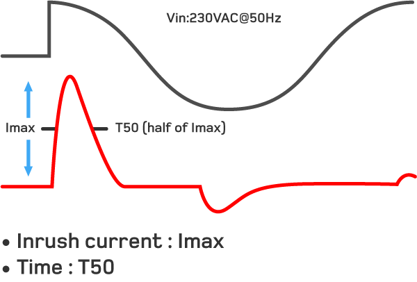
The lamp inrush current on switching LEDs has become an area of concern in the lighting industry. ‘Inrush current’ of the LED drivers refers to the input current of short duration that flows into the LED driver, during the initial start-up, to charge the capacitors on the input side. Typically, this is a short duration current, whose amplitude is much greater than the operating or steady-state current. The inrush current is due to the EMC filter on the input and bulk capacitor on the boost circuit this is inherent to the LED technology.
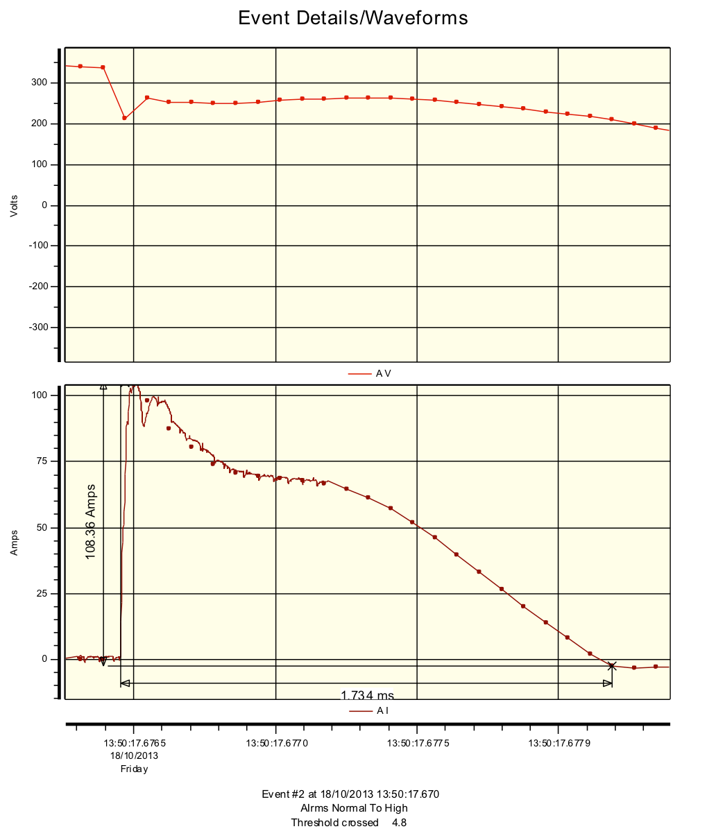
The figure shows the nature of the inrush current and its peak, IMAX. T50 is the time duration in which the inrush current pulse is equal to 50% of IMAX. It shows an example of inrush current (IMAX) and T50 times for a typical LED driver.
If there are a number of LED drivers in an LED Luminaire, and if there are a number of such LED Luminaires on one circuit, the max peak inrush current and it’s duration may be additive. However, it is not an exact mathematical calculation; i.e. “N” drivers connected in parallel does not equal exactly “N” times the inrush current for one driver or N times the T50 time for one driver. It depends on the impedance of each driver and the line impedance.
The line impedance has a significant effect on the peak and duration of the inrush current. Transformer type and size, wire size, length of runs, and other devices in the circuit path are a few things that could lead to high impedance.
The inrush current and the duration of the LED driver differs from manufacturer to manufacturer and from model to model. As this current duration is very small, sophisticated instruments with very high sampling rates need to be used for exact calculations. The inrush current also depends on the exact moment of switching, during the alternating cycle.
For a typical 150W, 0.7A LED driver, Philips Model 9137012116, used in various CREE luminaires, the inrush current is stated as 130Amp for 165 Micro Seconds. It is suggested that up to 7 -10 of these drivers be used / per 20A C curve MCB, however it will depend on the individual circuit impedance.
For a typical 220W, 1.05A LED driver, CREE Model LE098X01 used in CREE High Output Edge luminaires, the inrush current is stated as 80 Amp for 1000uS (1mS). It is suggested that up to 6 – 8 of these drivers be used /per 20A C curve MCB, however, it will depend on the individual circuit impedance.
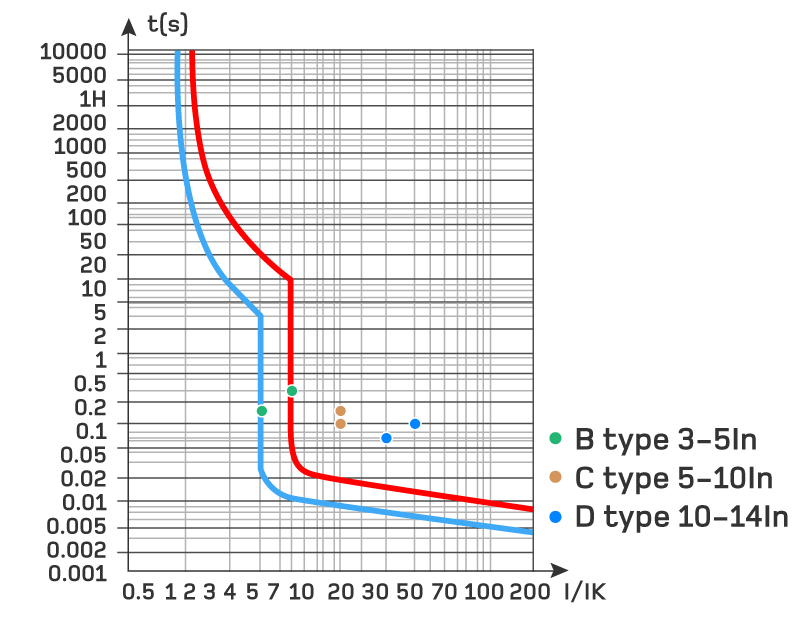
A general recommendation is to use C curve circuit breaker with the highest current rating that is allowed by the circuit cable size. The MCB used needs to have sufficient clearing time for the inrush current to clear, without creating the nuisance tripping on power up. This will give protection from a short circuit and prevent overheating of wiring and connections. MCBs operate by tripping open on detection of an overload or short circuit condition. The tripping point relates to the magnitude of electrical energy being passed – and this in turn depends significantly on both the inrush current peak value and its time duration. Accordingly, an MCB could be tripped either by a high peak of short duration, or a lower peak of longer duration. In either case, the objective is to ensure that the MCB trips before passing excessive energy, yet does not trip and cause lighting blackouts, when it does not need to.
Please see below, a typical MCB tripping curve showing the amount of time required for a circuit breaker to trip, at a given overcurrent level. These curves differ from manufacturer to manufacturer and from type to type. Typically, the B type MCB curve has the operating range of 3 to 5 In, C type has 5 to 10In and D type has 10-14 In.
Note: Many low-end relay systems in the lighting controls industry are designed for low inrush current lighting, without the consideration of high inrush LED technology. The high inrush on LEDs can cause these products to fail, by welding the relay contacts. Hence care must be taken that the photocells and occupancy sensors are rated suitably to handle the LED inrush currents, particularly in a retrofit solution. Advanced Lighting Technologies suggests using high quality photocell products able to handle the inrush current for LED products.
A typical example of the inrush current event has been presented below for easier understanding. This is to be taken as example of the inrush current captured at the time of test and not as absolute proof of correct values.
Disclaimer: The information provided in this document has been provided in good faith by ADLT. It is intended as a general guide only. ADLT welcomes any comments or feedback on this subject.
Professional advice should be sought before relying on the information provided. ADLT does not warrant accuracy of the information and disclaims any legal responsibility for any loss or damage which may be suffered directly or indirectly, by relying upon the information provided.
SPECIALISTS IN LED LIGHTING SOLUTIONS
Advanced Lighting Technologies (ADLT) has been a leader in the lighting market for over 25 years. With an established presence in Australia, New Zealand and Southeast Asia, we specialise in architectural, commercial and industrial lighting solutions designed for dozens of industries. Whatever the application, whatever the budget – we’ll have a solution that fits your needs.
Contact us for more information on an energy-efficient LED lighting solution today.

